
How Does an AC Circuit Breaker Curve C 10A 2P 6kA Support Safe Electrical Distribution?
Reliable circuit protection is essential for electrical systems used in industrial equipment, commercial facilities, and general power distribution. An AC Circuit Breaker Curve C 10A 2P 6kA is designed for applications that require a defined overcurrent response, a compact two-pole configuration, and an appropriate short-circuit breaking capacity. Understanding its electrical characteristics helps engineers select protection devices that match the operating conditions of their systems.
Choosing a circuit breaker involves more than checking its rated current. Engineers must also consider the connected load, starting current, supply characteristics, installation conditions, and coordination with upstream and downstream protection devices. These factors influence how effectively a protective device responds to electrical faults while allowing normal equipment operation.
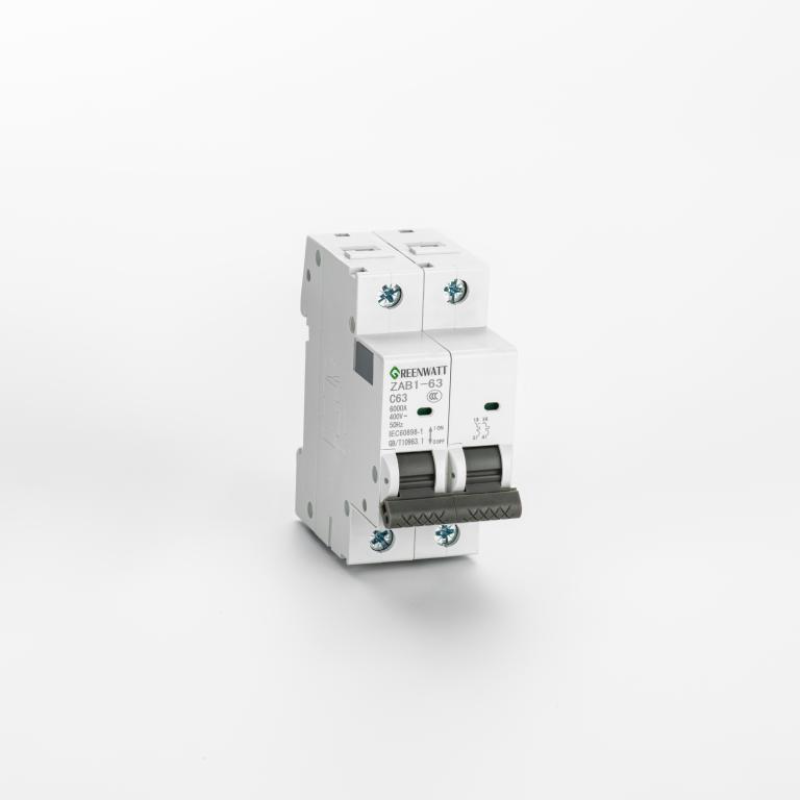
Understanding the Main Electrical Specifications
Circuit breakers are selected according to their intended electrical function and the characteristics of the circuits they protect. Each specification describes a different aspect of performance, so the complete combination should be evaluated rather than treating any single parameter as sufficient.
Rated Current and Load Requirements
The rated current indicates the current level for which a circuit breaker is designed under specified operating conditions. Selecting an appropriate rating requires an understanding of the normal operating current and the expected characteristics of the connected load.
- Calculate the expected operating current of the connected equipment.
- Consider the continuous operating conditions and potential changes in load demand.
- Check conductor ampacity and the applicable electrical installation requirements.
- Verify that the selected protective device is suitable for the circuit and its intended use.
A circuit breaker should not be selected solely because its rated current matches the normal operating current of a device. Cable capacity, ambient temperature, installation method, and other relevant correction factors may affect the final selection. Proper coordination between the protective device and the wiring system is necessary to reduce the risk of overheating and electrical damage.
Understanding the Curve C Tripping Characteristic
The tripping curve describes how a circuit breaker responds to overcurrent under specified conditions. Curve C devices are commonly used in circuits where connected equipment may produce moderate inrush currents during startup. Typical applications can include certain lighting circuits, general-purpose distribution circuits, and equipment with motor-related or transformer-related starting characteristics, provided that the device is suitable for the specific installation.
The thermal and magnetic tripping mechanisms perform different functions. The thermal mechanism responds to sustained overload conditions, while the magnetic mechanism provides rapid operation under sufficiently high fault currents. The actual response depends on the manufacturer's published time-current characteristics and the conditions in which the breaker operates.
- Thermal protection helps address sustained overcurrent conditions.
- Magnetic protection supports rapid interruption when current reaches the applicable instantaneous trip region.
- Time-current curves help engineers evaluate the relationship between fault magnitude and operating time.
- Load characteristics must be considered to reduce unwanted tripping during normal startup.
Curve selection requires careful evaluation. A curve that is suitable for one type of load may not provide the best performance for another. Engineers should compare the expected inrush current with the manufacturer's tripping data and confirm that the selected breaker can still provide the required protection under fault conditions.
Why a Two-Pole Configuration Matters
A two-pole circuit breaker provides switching and protection functions across two poles according to its design. This configuration is commonly considered for certain single-phase circuits and other arrangements where two conductors require coordinated switching. However, the exact suitability depends on the supply system, conductor arrangement, grounding method, and applicable electrical regulations.
When evaluating a two-pole device, engineers should verify which conductors are protected, how the poles operate together, and whether the device is approved for the intended circuit. A two-pole configuration should not automatically be interpreted as suitable for every single-phase or two-wire application.
- Confirm the circuit topology and supply arrangement.
- Check the manufacturer's terminal and wiring instructions.
- Verify the switching and isolation requirements of the installation.
- Ensure compliance with the relevant electrical codes and product standards.
Evaluating Short-Circuit Breaking Capacity
Short-circuit breaking capacity describes the level of fault current that a circuit breaker can safely interrupt under specified test conditions. It is an important consideration because the available fault current can vary significantly depending on the power source, transformer characteristics, cable impedance, and distance from the supply point.
The stated breaking capacity must be appropriate for the prospective short-circuit current at the installation location. If the available fault current exceeds the device's applicable breaking rating, the breaker may not be suitable for that position in the electrical system.
Matching Breaking Capacity to Installation Conditions
Engineers should determine or obtain the prospective short-circuit current at the point where the circuit breaker will be installed. The calculation or assessment should account for the electrical supply, conductor impedance, and other relevant system characteristics.
- Assess the prospective fault current at the installation point.
- Compare the result with the applicable rated short-circuit breaking capacity.
- Review the product's rated voltage and the conditions under which its breaking rating applies.
- Check whether a tested backup protection arrangement is required or permitted.
A higher breaking capacity may be necessary in installations supplied by low-impedance sources or in locations close to distribution transformers. In other installations, a lower-rated device may be adequate if the available fault current remains within the permitted limit. The decision should be based on verified electrical data rather than assumptions about the size or purpose of the equipment.
Breaking Capacity and Protection Coordination
Protection coordination helps ensure that the protective device closest to a fault operates as intended while limiting unnecessary interruptions elsewhere in the system. This is particularly important in facilities with multiple distribution levels, interconnected equipment, or circuits serving different operational functions.
Engineers may review time-current curves, instantaneous trip behavior, and the characteristics of upstream protective devices to assess coordination. Selectivity cannot be assumed simply because different breakers have different current ratings. Manufacturer coordination tables and relevant test data may be needed to verify the performance of a particular combination.
| Specification | Engineering Purpose | Selection Consideration |
|---|---|---|
| Rated current | Defines the intended current rating of the device | Normal load, cable capacity, and installation conditions |
| Curve characteristic | Describes the overcurrent response | Load inrush and fault-clearing requirements |
| Pole configuration | Defines the switching arrangement | Supply topology and conductor requirements |
| Breaking capacity | Defines the applicable short-circuit interruption capability | Prospective fault current and rated operating conditions |
| Rated voltage | Defines the voltage conditions for intended operation | System voltage and manufacturer specifications |
Common Applications in Electrical Installations
Compact circuit breakers are used in a wide range of electrical distribution arrangements. Their suitability depends on the load, system voltage, fault level, enclosure design, and applicable standards. Correct application begins with identifying the electrical function of the circuit rather than choosing a device based on physical size alone.
Commercial Buildings and General Distribution
Commercial buildings contain lighting systems, socket circuits, control equipment, and various auxiliary loads. Circuit breakers help protect these circuits against abnormal current conditions and provide a means of switching when the product is designed and approved for that purpose.
During selection, engineers should consider the characteristics of the connected loads, the continuity requirements of the facility, and the arrangement of the distribution board. Circuits supplying electronic equipment may have different inrush and leakage characteristics from circuits serving conventional resistive loads.
Distribution designs should also account for conductor identification, terminal accessibility, enclosure temperature, and adequate spacing. These details contribute to safer installation and easier maintenance throughout the operating life of the electrical system.
Industrial Control Panels
Industrial control panels combine power distribution, control devices, instrumentation, and other electrical components. Protective devices within these assemblies must be compatible with the panel's electrical design and the characteristics of the equipment being supplied.
- Evaluate the starting behavior of connected motors and other inductive loads.
- Check the fault current available at the panel supply.
- Review the coordination of branch-circuit and upstream protection.
- Confirm the temperature and enclosure conditions under normal operation.
- Follow the panel manufacturer's wiring and assembly requirements.
For industrial applications, the choice of a tripping characteristic should be supported by load data. A device with an unsuitable instantaneous response may trip during normal startup, while an unsuitable protection arrangement may fail to provide the intended fault response. Engineering verification is therefore essential before installation.
Auxiliary Circuits and Electrical Equipment
Auxiliary circuits support functions such as control power, signaling, monitoring, and equipment accessories. Although these circuits may carry less current than the main power circuit, their protection remains important for reliable operation and safe fault isolation.
Engineers should review the load's operating current, sensitivity to power interruption, and possible inrush behavior. For electronic power supplies, capacitive input circuits, and control transformers, startup current can differ from steady-state current. The manufacturer's technical information should be used to confirm compatibility with the selected breaker.
Where equipment is installed in a compact enclosure, thermal conditions and terminal arrangements also require attention. Proper spacing, suitable conductor sizing, and secure connections help reduce the likelihood of overheating and avoid unnecessary maintenance issues.
Installation Practices and Technical Verification
Correct product selection is only one part of an effective electrical protection strategy. Installation quality, wiring accuracy, and inspection procedures also influence system reliability. Even a correctly rated circuit breaker can perform poorly if it is installed in an unsuitable environment or connected contrary to the manufacturer's instructions.
Pre-Installation Checks
Before installation, the electrical design and product documentation should be reviewed to confirm compatibility with the intended application. The device's rated voltage, current, tripping characteristic, pole arrangement, breaking capacity, and mounting requirements should all be considered.
- Verify the product identification and technical documentation.
- Confirm the circuit's operating voltage and expected load current.
- Check the prospective short-circuit current at the installation location.
- Inspect the distribution enclosure and mounting arrangement.
- Confirm conductor type, cross-sectional area, and terminal compatibility.
- Review applicable standards and local electrical regulations.
Where the circuit forms part of a larger installation, coordination with upstream and downstream devices should be evaluated. This can involve checking manufacturer data, time-current curves, and any relevant tested combinations. If the installation has unusual operating conditions, additional engineering review may be necessary.
Wiring and Connection Quality
Electrical connections should follow the manufacturer's instructions, including the specified conductor preparation, terminal arrangement, and tightening requirements. Loose connections can create localized heating, while incorrect wiring can affect the intended operation of the protection system.
Installers should verify that conductors are connected to the correct terminals and that the device is securely mounted. The enclosure should provide appropriate protection against accidental contact and environmental influences. Where required, circuit identification should be clear and consistent with the electrical drawings.
Before energizing the installation, qualified personnel should complete the inspections and tests required by the applicable regulations and commissioning procedures. Testing should be performed with suitable instruments and methods, following safe isolation practices and the manufacturer's guidance.
Environmental and Thermal Considerations
Ambient temperature, ventilation, enclosure density, and nearby heat sources can influence the operating conditions of electrical protection devices. A distribution board containing many closely installed components may experience a different thermal environment from a well-ventilated assembly with fewer devices.
Engineers should review any applicable derating requirements and ensure that the device operates within the manufacturer's specified conditions. Dust, moisture, vibration, and corrosive substances may also affect equipment suitability, depending on the installation environment and the protection provided by the enclosure.
In demanding industrial locations, a suitable enclosure and appropriate installation practices can help protect electrical components from environmental exposure. However, enclosure protection should not be treated as a substitute for verifying the circuit breaker's own environmental and operating limits.
Maintenance and Operational Reliability
Routine inspection helps identify developing issues before they cause unexpected interruptions. The maintenance approach should reflect the installation's operating environment, equipment criticality, applicable regulations, and the manufacturer's recommendations.
Inspection of Electrical Assemblies
Maintenance personnel can examine the surrounding assembly for signs of overheating, discoloration, damaged insulation, contamination, or loose mounting. Any abnormal condition should be investigated by qualified personnel using appropriate safety procedures.
- Check for visible signs of heat damage or insulation deterioration.
- Inspect terminal areas for discoloration or other indications of abnormal heating.
- Confirm that circuit labels remain legible and match the electrical documentation.
- Review the enclosure for dust accumulation, moisture, or mechanical damage.
- Investigate recurring trips instead of repeatedly resetting the device without diagnosis.
A circuit breaker that trips repeatedly may be responding correctly to an overload or fault. Repeatedly restoring power without identifying the cause can expose equipment and wiring to additional risk. The circuit should be assessed to determine whether the problem involves excessive load, a short circuit, an equipment defect, or an unsuitable protection arrangement.
Replacement and Product Compatibility
When a circuit breaker needs replacement, matching the original rated current alone is not sufficient. The replacement should be compatible with the system voltage, pole configuration, tripping characteristic, breaking capacity, mounting arrangement, and relevant product standards.
Changes to the circuit design may require a new assessment of conductor capacity and protection coordination. In addition, physical compatibility with a distribution board does not automatically establish electrical suitability. Replacement decisions should be based on technical documentation and the requirements of the complete installation.
For equipment operating under demanding conditions, maintenance records can help identify recurring faults and support decisions about inspection intervals or system upgrades. Clear documentation also helps technicians verify that replacement components meet the original design requirements.
Manufacturing Quality and Product Consistency
Reliable circuit protection depends on product design, component quality, manufacturing accuracy, and appropriate verification. Consistent production processes help manufacturers control dimensions, assembly quality, and the repeatability of important operating characteristics.
Electrical protection products contain mechanical and electrical elements that must work together. The performance of the complete assembly can be affected by material selection, contact construction, thermal behavior, internal clearances, and the accuracy of the operating mechanism. Manufacturing controls are therefore important throughout the production process.
Role of Mold Making and Metal Processing
Supporting manufacturing capabilities can contribute to the consistency of electrical components. Metal stamping is used to produce shaped metal parts, while mold making supports the production of components with defined dimensions and repeatable geometry. Thermosetting compression molding can be used for suitable insulating or structural parts, depending on the material and product design.
These processes require appropriate tooling, material control, and production inspection. Dimensional accuracy is important because electrical components must fit correctly within an assembly and maintain the required mechanical relationships. Material properties also need to match the intended thermal, mechanical, and electrical conditions.
- Tooling accuracy supports consistent component dimensions.
- Controlled material selection helps meet design requirements.
- Process inspection helps identify manufacturing variation.
- Assembly verification supports repeatable product quality.
- Technical documentation improves traceability and production control.
Testing and Compliance Considerations
Electrical protection devices should be evaluated against the standards and requirements applicable to their intended market and application. Relevant verification may cover electrical performance, dielectric properties, temperature rise, mechanical operation, and short-circuit interruption, depending on the product category and governing standard.
Product documentation should clearly identify the applicable ratings and conditions of use. Technical data should be consistent with the actual product configuration and supported by appropriate test evidence. Where certification or third-party assessment is required, the scope and validity of the relevant documentation should be confirmed rather than assumed.
Manufacturers also benefit from clear feedback channels between design, production, quality management, and technical service. This helps ensure that product changes are reviewed appropriately and that manufacturing processes remain aligned with the intended performance requirements.
How to Compare Circuit Breaker Options
When comparing products for a new project or replacement application, engineers should use a consistent technical review process. A structured comparison reduces the risk of overlooking important differences between devices that may appear similar in their basic descriptions.
Review the Complete Specification
The product description should be checked against the actual circuit requirements. Rated current and tripping characteristic provide useful starting information, but they do not replace the need to evaluate voltage, breaking capacity, pole arrangement, mounting compatibility, and applicable standards.
| Review Area | Information to Confirm | Why It Matters |
|---|---|---|
| Electrical ratings | Current and rated operating voltage | Supports compatibility with the supply and connected load |
| Fault protection | Tripping data and breaking capacity | Helps establish suitability under abnormal conditions |
| Installation | Pole arrangement and mounting dimensions | Supports correct integration into the electrical assembly |
| Operating environment | Temperature and enclosure conditions | Helps confirm compliance with operating limits |
| Documentation | Technical data and applicable conformity records | Supports engineering review and installation verification |
Consider the Complete Service Life
Product evaluation should include installation, operation, maintenance, and replacement requirements. A device that fits the initial design but lacks suitable documentation or does not meet the actual fault level can create additional engineering and maintenance work.
Clear technical specifications help engineers compare alternatives and identify differences that may affect application suitability. For projects with specialized requirements, reviewing drawings, product data sheets, and coordination information with the manufacturer can help resolve uncertainties before the equipment is installed.
It is also important to distinguish between a product's general application range and its verified performance under specific conditions. General descriptions provide useful background, while final selection should rely on the relevant ratings, test information, and installation requirements.
Developing Safer and More Reliable Power Distribution Systems
Electrical infrastructure continues to evolve as industrial automation, commercial equipment, and distribution systems become more integrated. This development places ongoing emphasis on reliable protective devices, consistent manufacturing quality, and careful engineering review.
Effective protection begins with understanding the electrical load and the fault conditions that may occur. It also requires appropriate conductor selection, verified breaking capacity, suitable tripping characteristics, and coordination with other protective devices. Installation quality and maintenance practices remain essential throughout the service life of the system.
An AC Circuit Breaker Curve C 10A 2P 6kA should therefore be evaluated as part of the complete electrical design rather than as an isolated component. Its suitability depends on whether its rated characteristics meet the requirements of the actual circuit, including the expected load behavior, supply voltage, available fault current, and installation environment.
Zhejiang Dongan Electrical and Low-Voltage Manufacturing
Zhejiang Dongan Electrical Co., Ltd. is a professional electrical manufacturer integrating design, production, sales, and service. With nearly thirty years of industry experience, the company focuses on the development and manufacturing of low-voltage electrical products for industrial, commercial, and power distribution applications.
The company's product range includes AC MCCB, AC ELCB, AC ACB, and DC MCCB, supporting different circuit protection requirements. In addition to finished electrical products, Zhejiang Dongan Electrical provides supporting manufacturing services such as thermosetting compression molding, metal stamping, and mold and parts manufacturing.
The combination of electrical product development and supporting production capabilities allows the company to serve a range of low-voltage electrical applications. For technical evaluations, product selection should be based on the required electrical ratings, application conditions, and relevant product documentation.
By continuing to focus on low-voltage electrical manufacturing and related production processes, Zhejiang Dongan Electrical Co., Ltd. supports the development of practical circuit protection solutions for diverse electrical systems. Its experience in product manufacturing and supporting services provides a foundation for addressing the technical requirements of industrial, commercial, and power distribution applications.